|
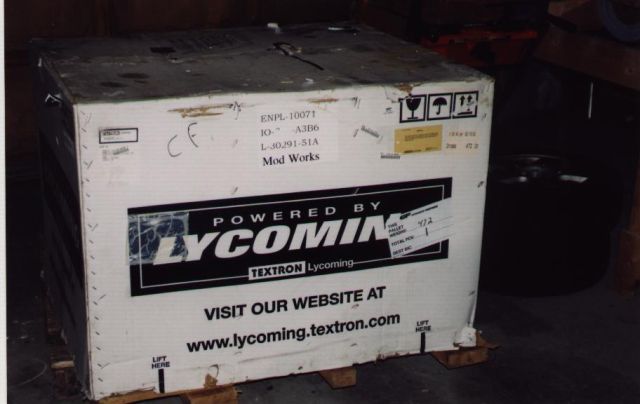
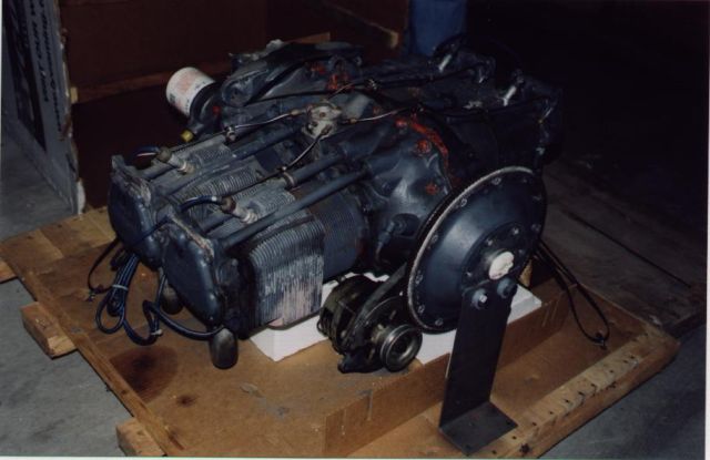
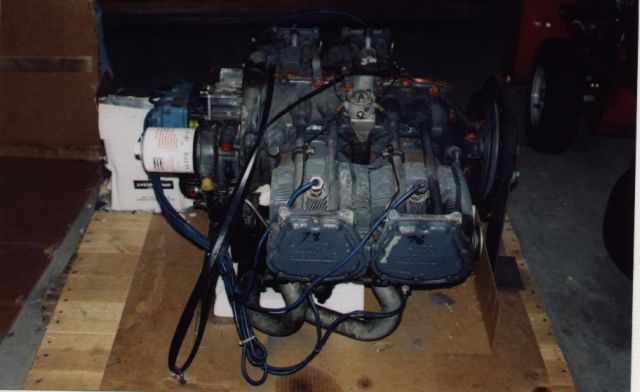
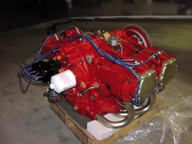
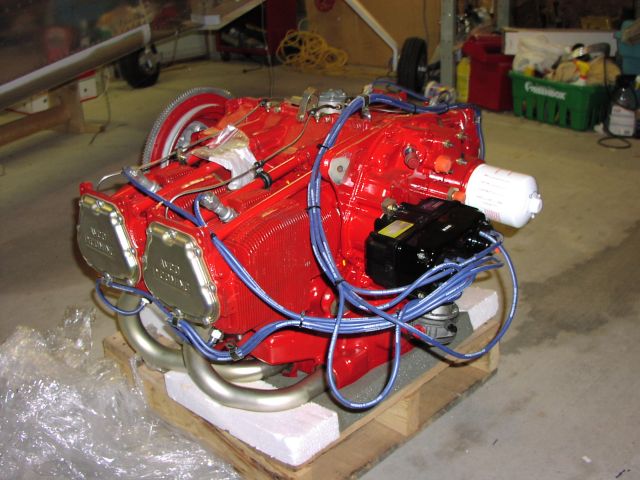
I had planned on using the Eggenfllner Subaru, but some concerns about making the heater fit in the fuse, and the opportunity to get a used IO-360-A3B6D at a good price swayed me. Here are some pics of my used engine the day that it arrived.
|
|
|
|
|
|
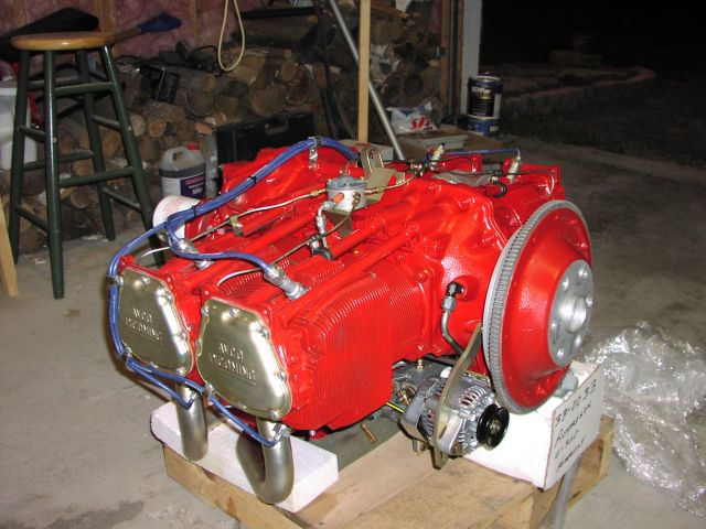
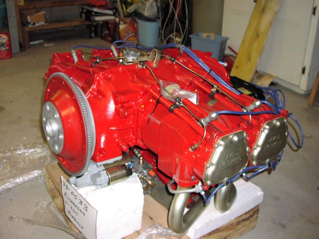
And after the overhaul by Leavens in Toronto....
|
|
|
|
|
|
|
|
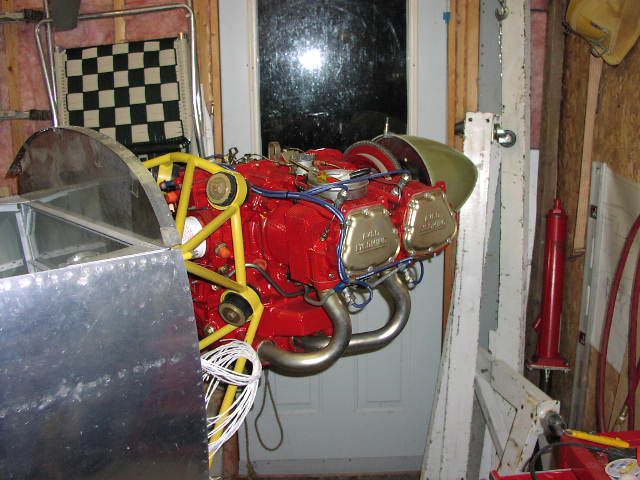
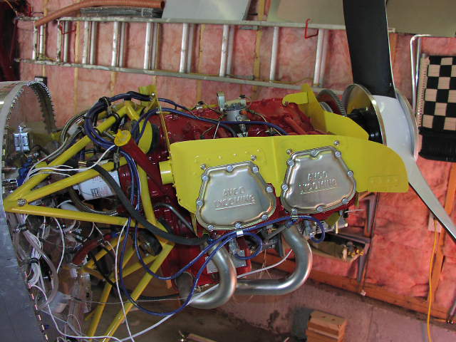
And here it is hangin on the front of the airplane. You can see some of the wires hanging off the firewall. I got a little ahead of myself with these pictures. The ones that follow show the firewall set up.
|
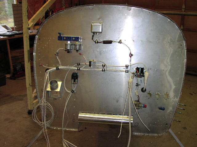 |
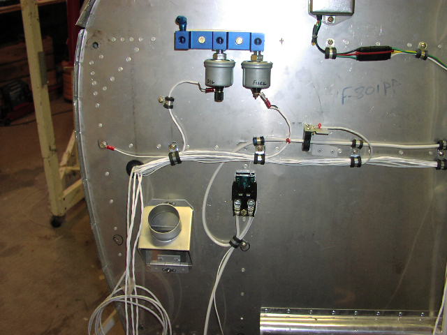
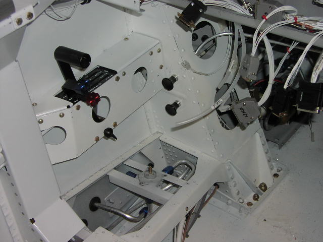
Overall firewall view. Pretty much everything that needs to be installed is on the firewall in this picture. I'm mounting the oil cooler on the right baffle (see explanation with the baffle pics below), and I'm not bothering with an oil seperator for now. I've heard it said that running the hose back into the oil sump from the oil seperator is like running a hose from your rectum to your mouth. YUCK. I'll just run the overflow to the exhaust pipe. |
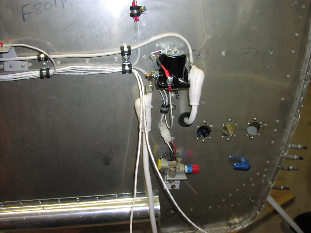 |
The starter contactor and fuel flow sensor (I'm using the RMI uMonitor). You can see where the alternator feed comes from the left side of the picture and attaches on the battery side of the contactor. The two thin, dangling wires are for the mag P-Leads. The honkin' 2AWG wire goes to the starter. |
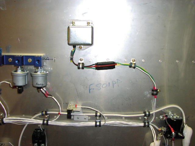 |
The high tech, automobile voltage regulator from Van's. The yellow wire out of the regulator is capped and stowed (not required). I went to Canadian Tire (kinda like Pep Boys/Ace Hardware/Home Dumpo all rolled into one without the building suppleis) and got a trailer light lead. I butt spliced in the regular wires and voila.
The weird little gizmo in the bottom centre is the sensor for the RMI uMonitor ammeter. I don't like how it is mounted, and may change it. |
 |
That black thingy in the centre if a 60 amp fuse block, again from Canadian Tire. The 8 AWG wire comes from the alternator, passes through the fuse, and heads on over to the battery side of the starter contactor. |
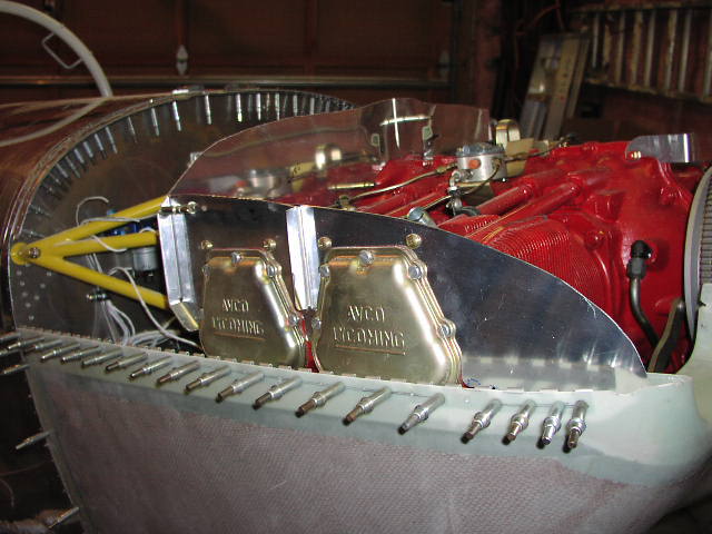 |
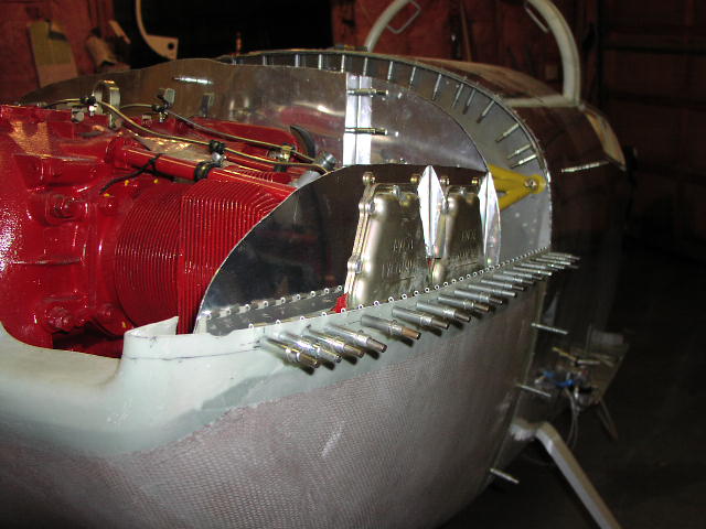
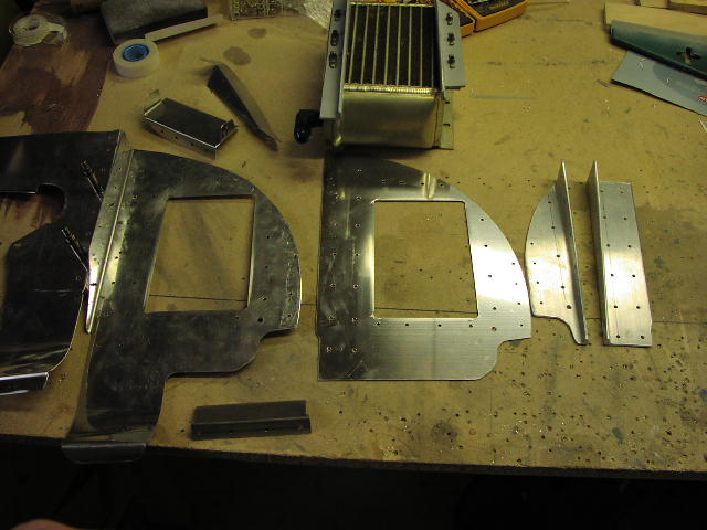
Here's a pic of the initial trimming of the baffles. I haven't yet attached the reinforcing plates, as I knew they would have to be trimmed above each cylinder, especially on the left. This whole initial trimming process wasn't the horrible job I was expecting. I put the rear baffles on (there was a problem with those, however, see below), put the top cowl on, and reached through the oil door cut out to mark the contour on the rear baffles, 1/2" at a time. I trimmed the baffles with aviation snips right on the plane. Mark, trim, check, mark, trim , check, etc... |
 |
Here you can see how close I had to trim the baffle material on the left side. It appears to be a chronic issue with IO-360-A's. I'm hopeful I can still attach the gasket material to this somehow. |
 |
Here is a closer look at the left side. Not much space, eh ? |
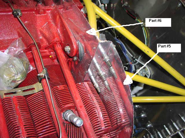 |
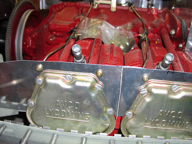
This is where I ran into a real fit problem. Part #5 (the left most rear baffle) goes across the back of cylinder #4 and has a large flange that wraps forward around the base of the cylinder. Part #6 (the next rear baffle in heading to the center of the engine) also has a flange that goes forward, and the two forward pointing flanges are supposed to be rivetted together. Uh.... nope. The flange on my part #6 was pressed hard against the base of cylinder #4, and the flange from part #5 couldn't fit in there. Since all of the other holes and cutouts are already made in part #6, and it fit well otherwise, I had to cut the flange off, and put a piece of angle in there. Now it fits fine. |
 |
A rear view of where I needed to put in the angle piece. I haven't cleaned up any edges here, so they all look a little rough.
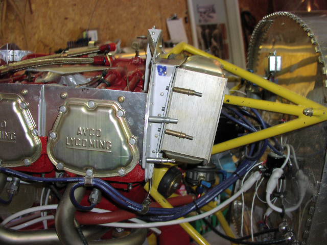
Up until recently, I was going to put my oil cooler on the behind cylinder #3. There appeared to be a ton of room, until I really looked close. It was going to interfere with the oil dipstick, or at least be really close. I I didn't want to be burning my arm and hand when I checked the oil right after shutting down, so I guess I'm back to plan A, behind #4 cylinder. |
 |
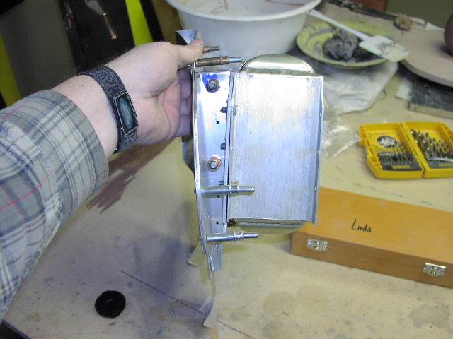
Here is a rather dark picture of the parts for my oil cooler mount (the flash didn't go off). I don't want this puppy to break, so I made a REALLY big doubler plate out of .040. The angle is 1 1/4 x 2 .125 thick. |
 |
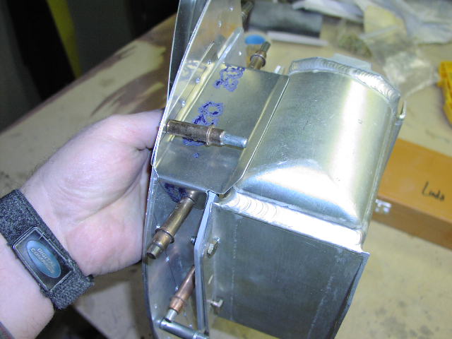
Here it is clecoed together. That weird looking thing going across the top of the baffle is an idea I swiped off of Dan Checkoway's site. It allows you to run a continuous piece of baffle material across the back of the engine without the pain in the butt intersection. |
 |
Here is a better view of the baffle material gap filler. Note that there is a piece of aluminum folded under. A little RTV and that will completely seal off the area. |
 |
Here is a side view. See that lump in the back of the picture that kinda looks like dog do-do ? Well, it isn't. Linda has a pottery studio in the basement, and she uses half of the workbench, and I use the other half. |
 |
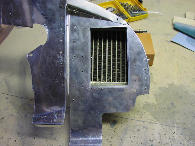
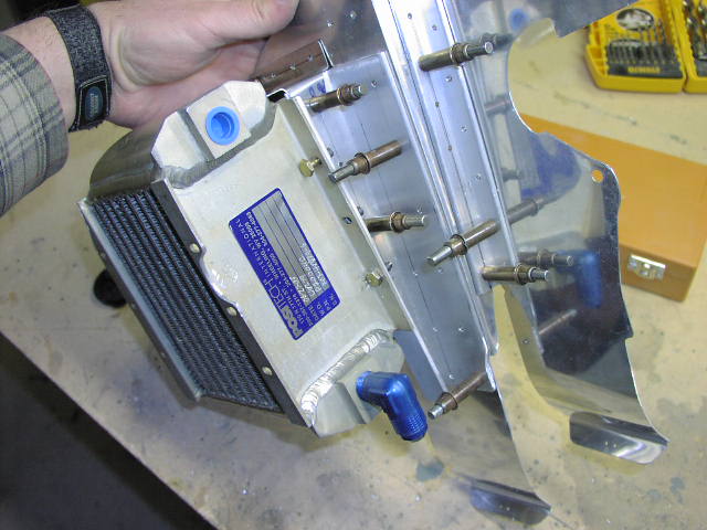
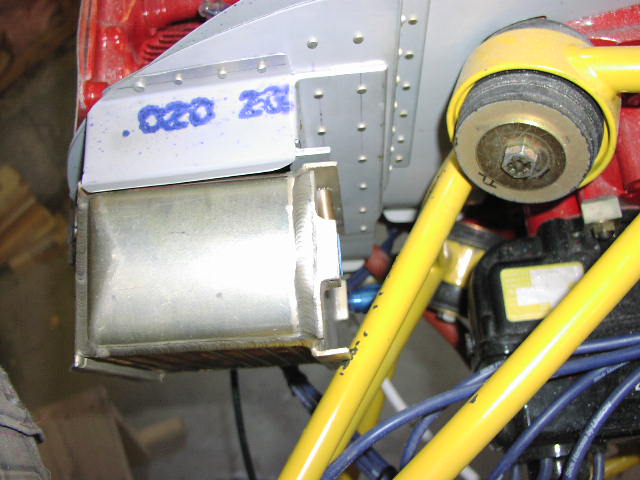
This is a seal I made out of aluminum (.020). I made the part out of cardboard first, then used that as a template. The idea is that when I finally put the oil cooler on the mount permanently, I'll seal around the edges with RTV, including the gap you can see here in the corner of the cooler. WIth those sealed, all of the air has to pass throught the cooler before exiting. |
 |
Here's a picture of the other side of the cooler. |
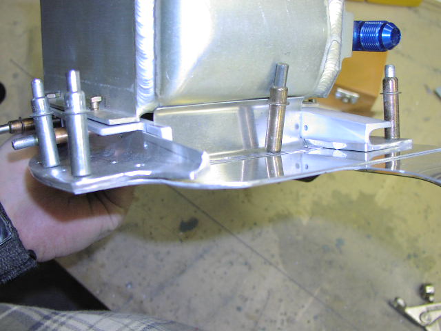 |
This is another seal I made, but for the bottom. Same deal; a little RTV and it is completely sealed. |
 |
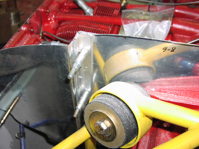
And here it is mounterd on the airplane. |
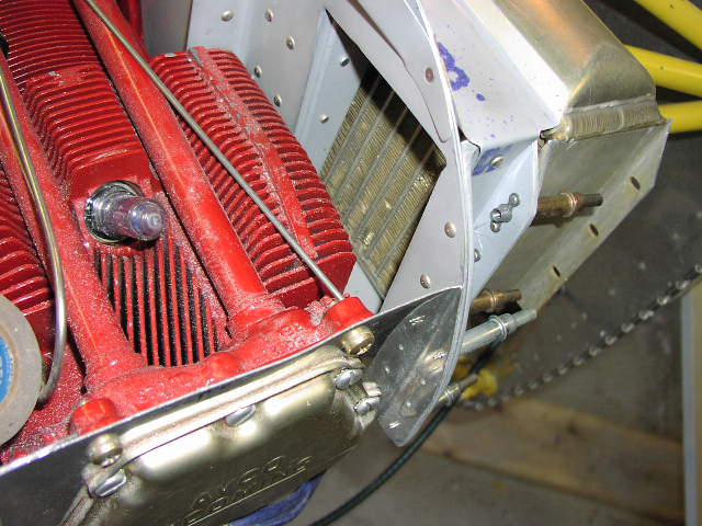 |
With this shot, you can see that the cooler is pushed back from the baffle, allowing more air space between the fins of the #4 cylinder and the cooler itself. |
 |
A rear view shot of the mounted cooler. There are just clecoes holding it on in these pictures, this it isn't tight up against the mount. |
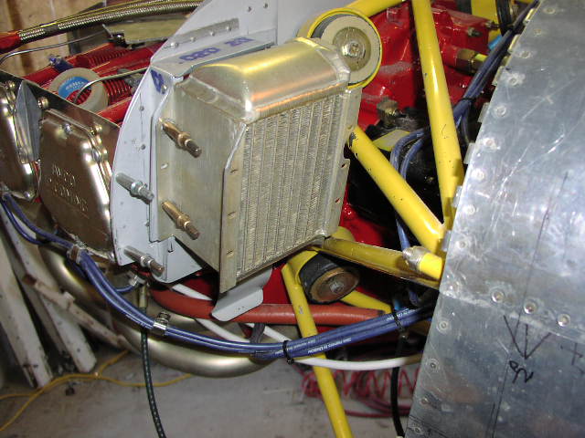 |
And another shot of it mounted. Note that I banged the hell out of the paint on the mount where the cut out is made in the cooler flange ;-( |
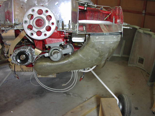 |
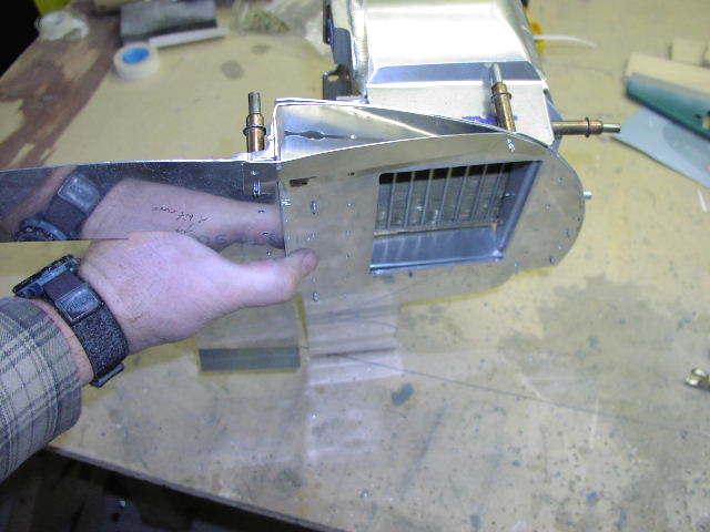
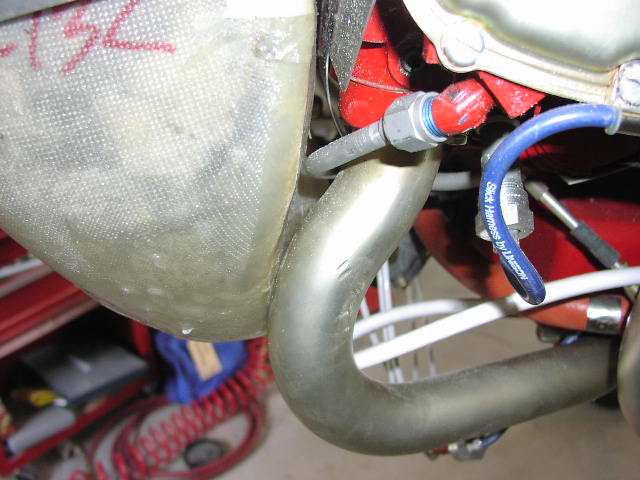
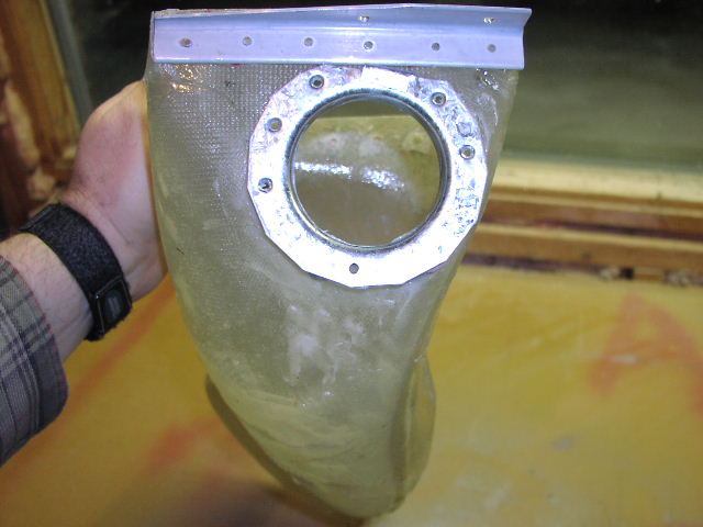
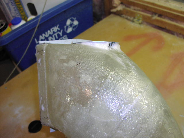
Here is a shot of the induction snorkel in place, but without the hole cut in the inlet ramp. |
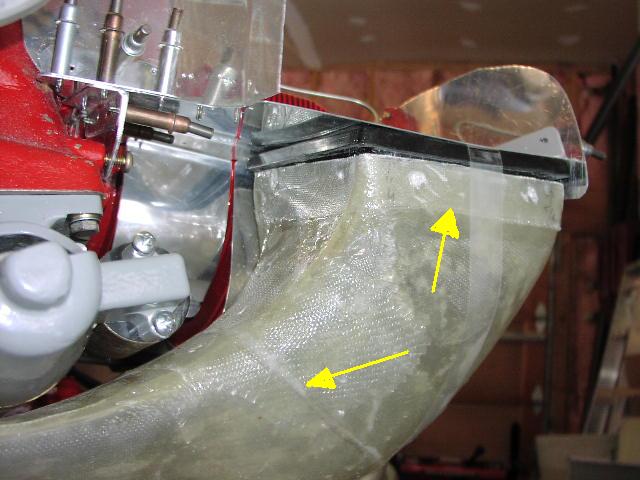 |
The yellow arrows indicate where I performed surgery on the snorkel. The one on the left is where I had to take a wedge shaped piece out of the snorkel and bend it in more such that it fit inside the left side baffle. The arrow on the right shows where I cut off too much of the lip and had to put more material back on. What a loser ;-) |
 |
This is a major pain. There is only one hole in my fuel injector that I can get at from behind to mark the holes in the snorkel itself (the one in the bottom left of the picture). I marked the first one (OK, the second one. You can see the first one was wrong and I needed to mark another), then used a pencil rubbing of the face of the fuel injector to find the other holes, then used that as a template on the snorkel. Close, but I have some tweaking to do. |
 |
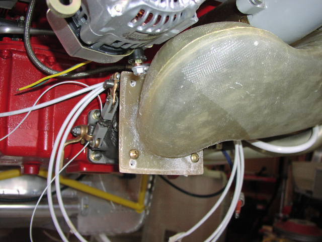
Lots of space under the starter. |
 |
The oil return line needed to be removed and bent a bit. Easy job that took 5 minutes. |
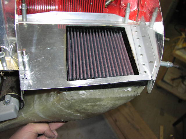 |
And here is the cut out for the snorkel. You'll note that the hole looks like a trapezoid. Well, it is more of a parallelogram (the picture angle just makes it look funny). The inlet ramp has a twist in it (not unusual I hear), thus the filter is twisted when pressed up from underneath. That is what causes the trapezoid shape. |
 |
Here is a shot of the alternate air door mount. It is held on with 5 AD-42H pop rivets (the same ones you use in the tanks). |
 |
Here's a side view where you can see the filler to keep the whole thing from vibrating itself to death. |
 |
And the other side. You can just see the platenut that holds the AN515-8R8 screw which functions as the pivot point for the door. |
 |
The top black knob is the Bowden cable for my cabin heat. The bottom one is for the alternate air. |
 |
Here you can see the cable heading towards the firewall. You can also see two black grommets that don't have anything coming through them. They're lightening holes, OK !!! Get off my back ;-) |
 |
Here you can see the alternate air cable exiting the firewall and coming forward to the door. The cable is attached to the door by countersinking the inside of the door, putting a countersunk #6 screw through, wrapping the inner part of the cable around the screw 3 times, and tightening up the screw with a nut. Low tech, but it works great. |
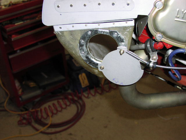 |
And finally you can see the door in an open position. |
 |
Here is a shot of the baffles finally installed. I have cut out poster board mock-ups of the gasket material, but haven't put it on yet. |
 |
A little dark, but a front end view of the installed baffles. |
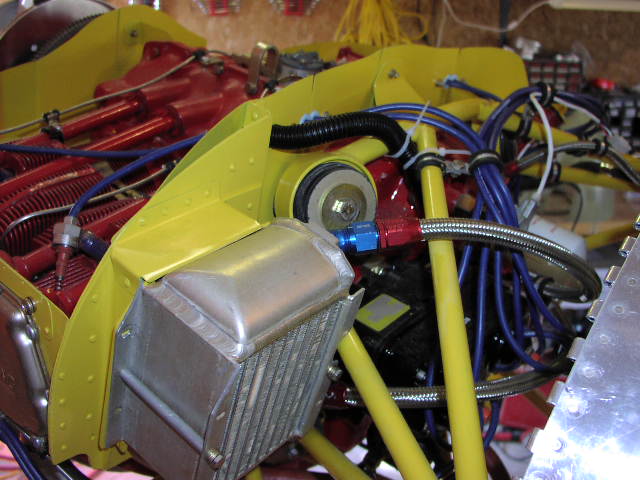 |
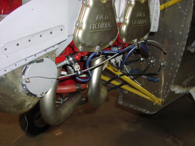
And the final oil cooler installation. Didn't turn out too bad. |